- Nadine Homeyer and Holger Gohlke, 原始文档
- 2018-03-26 21:44:05 翻译: 周盛福
请注意: 此处介绍的FEW工具可以在AmberTools 14或更高版本中获取, 并可与AmberTools和AMBER 14或更高版本一起使用. AmberTools和AMBER 14可以按照AMBER手册中的安装指导进行安装. 在安装过程中会自动修复BUG并获取更新补丁.
FEW工具可用于自动配置与同一受体结合的一系列配体的结合自由能计算, 本教程旨在演示该功能. FEW工具支持的设置自由能计算的方法有: 基于分子力学的泊松-玻尔兹曼表面积(MM-PBSA)模型、基于分子力学的广义波恩表面积(MM-GBSA)模型, 线性相互作用能(LIE)模型和热力学积分(TI)模型方法. 在使用FEW工具之前, 您应该熟悉在AMBER中运行基本的分子动力学(MD)模拟以及您希望采用的自由能计算方式的理论和设置. 演示分子动力学模拟的设置与运行和通过MM-PB(GB)SA及TI方法计算自由能的教程可以在http://ambermd.org/tutorials中找到. 关于自由能计算方法的理论解释可以参考相关综述和书籍: MM-PB(GB)SA [1, 2], LIE [3, 4]和TI [5, 6]. 此外, 强烈建议阅读文献N. Homeyer, H. Gohlke, FEW - A Workflow Tool for Free Energy Calculations of Ligand Binding. J. Comput. Chem. 2013, 34, 965-973. 本文中演示的自由能计算示例就是选自这篇文献介绍的研究案例. 我们确定了3种在凝血级联反应中起重要作用, 抑制蛋白酶因子Xa的配体的相对结合自由能(表1).
需要的输入结构:
- 受体的PDB结构, 即因子Xa蛋白
- 已将坐标定义到结合口袋的配体结构(mol2格式)
如果配体的结合模式是未知的, 则可以通过类似配体的结合模式构建或通过对接程序获取. 在这里显示的样本分析中, 使用了前一策略. 请注意, 结合自由能预测的准确度随着蛋白质结构质量的下降和配体结合模式的不确定性而降低. 因此, 应该使用高质量的蛋白质(即受体)结构, 并且配体的结合位置应尽可能准确地构建.
表1 因子Xa的配体结构和实验检测的Ki值(nM)
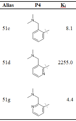
准备工作
为了便于在本教程中使用FEW工具, 请设置一个变量$FEW指定FEW在您系统上的安装路径, 例如:
setenv FEW = /home/src/FEW		(对于csh或tcsh)或
export FEW = /home/src/FEW		(用于bash、zsh、ksh等)
在定义环境变量后执行echo $FEW, 就应该显示FEW安装路径.
本教程中使用的输入文件可以在这里下载. 在解压文件之后, 按照README文件中的安装说明, 本教程所需的文件应位于$FEW/examples/tutorial目录下.
现在, 请创建一个新的文件夹, 并进入到此文件夹中. 在本教程中, 我们假设新文件夹名为tutorial, 位于/home/user/tutorial. 以下教程中, 您需要根据您的系统上创建的tutorial文件夹的位置来调整路径.
现在, 将文件夹input_info(包含所有需求的输入文件), structs(包含Mol2格式的配体结构)和cfiles(包含FEW的命令文件)复制到您创建的tutorial文件夹中:
cp -r $FEW/examples/tutorial/input_info .
cp -r $FEW/examples/tutorial/structs .
cp -r $FEW/examples/tutorial/cfiles .
现在, 在本地文件夹中我们已经有了所有需要的数据, 因此我们可以开始使用FEW工具来设置自由结合能计算了.
第一节: 分子动力学(MD)模拟的设置
MM-PB(GB)SA和LIE计算是基于MD模拟的轨迹快照进行的. 因此, 在开始这些类型的自由能计算之前, 需要执行该步骤. TI计算可以直接从晶体结构开始, 但通常建议首先运行一个短的MD平衡来消除结构中不好的接触. 因此, 只有后面的步骤将在这里演示. 对于之前的步骤, 请参阅AMBER手册的FEW部分.
在这里, MD模拟被分成两步设置, 首先确定配体的参数(步骤1A), 然后产生MD模拟的输入文件(步骤1B). 图1展示了这两个步骤所需的输入信息和FEW生成的输出信息.
注意: 为了演示的目的, 在本教程中将分别设置复合物、受体和配体的MD模拟(3-轨迹方法). 如果您希望根据“1-轨迹方法”只进行MM-PB(GB)SA计算(即无LIE或TI计算), 则建议此时只设置复合物的模拟.
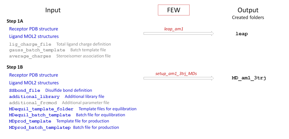
图1: 使用FEW进行MD模拟设置的示意图. 本教程中使用的输入信息以蓝色显示, 对于其他体系/参数设置时, 可能需要的输入数据以灰色显示, FEW的命令文件以红色字体标出. 本例中未使用到的输入文件(上图中的灰色部分)可以在文件夹``$FEW/examples/input_info中找到, 并且AMBER手册的FEW部分提供了这些数据的解释.
A: 参数文件的准备
MD模拟的设置是从定义所需的参数以及重新格式化输入结构文件开始的. 为此, 我们使用文件夹/home/user/tutorial/cfiles中的命令文件leap_am1.
| bash | |
|---|---|
1 2 3 4 5 6 7 8 9 10 11 12 13 14 15 16 17 18 19 20 21 22 23 24 25 26 27 28 29 30 31 32 33 34 35 36 37 38 39 40 41 42 43 44 45 46 47 48 49 50 51 52 53 54 55 56 57 58 59 60 61 62 63 64 65 66 67 68 69 70 71 72 73 | @WAMM
################################################################################
# Location and features of input and output directories / file(s)
#
# Location and features of input and output directories / file(s)
#
# lig_struct_path: Folder containing the ligand input file(s)
# multi_structure_lig_file: Basename of ligand file, if multi-structure
# file is provided
# output_path: Basis directory in which all setup and analysis
# folders will be generated
# rec_structure: Receptor structure in PDB format
# bound_rec_structure: Optional, alternative receptor structure in bound
# conformation to be used for 3-trajectory approach
lig_struct_path /home/user/tutorial/structs
multi_structure_lig_file
output_path /home/user/tutorial
rec_structure /home/user/tutorial/input_info/2RA0_IN.pdb
bound_rec_structure
# Specification of ligand input format
lig_format_sdf 0
lig_format_mol2 1
# Receptor features
# water_in_rec: Water present in receptor PDB structure
water_in_rec 1
# Request structure separation
# structure_separation: Separate ligands specified in one multi-structure # input file and generate one structure file per ligand.
structure_separation 0
################################################################################
# Creation of LEaP input files
#
# prepare_leap_input: Generate files for LEaP input
# non_neutral_ligands: Total charge of at least one molecule is not zero.
# In this case the total charge of each non-neutral
# molecule must be defined in lig_charge_file.
# lig_charge_file: File with information about total charges of ligands.
# am1_lig_charges: Calculate AM1-BCC charges.
# resp_lig_charges: Calculate RESP charges. In this case charges must be
# computed with the program Gaussian in an intermediate step.
# Batch scripts for Gaussian calculations will be prepared
# automatically, if requested (see prepare_gauss_batch_file
# and gauss_batch_template below).
# calc_charges: Calculate charges according to requested procedure.
# If this flag is set to zero, no atomic charges are calculated.
# resp_setup_step1: Step 1 of RESP charge calculation: Preparation of
# Gaussian input.
# resp_setup_step2: Step 2 of RESP charge calculation: Generation of LEaP input # from Gaussian output.
# prepare_gauss_batch_file: Generate batch script for Gaussian input if RESP
# charge calculation is performed. A batch template
# file (gauss_batch_template) is required.
# gauss_batch_template: Batch template file
# Prerequisite: resp_lig_charges=1, resp_setup_step1=1
# and prepare_gauss_batch_file=1
# gauss_batch_path: Basic working directory for Gaussian jobs
# average_charges: If the charges of two steroisomers shall be averaged, so that
# both ligands obtain the same atomic charges, a file in which
# the stereoisomer pairs are specified must be given here.
prepare_leap_input 1
non_neutral_ligands 0
lig_charge_file
am1_lig_charges 1
resp_lig_charges 0
calc_charges 1
resp_setup_step1 0
resp_setup_step2 0
prepare_gauss_batch_file 0
gauss_batch_template
gauss_batch_path
average_charges
|
leap_am1文件可以直接用作FEW的输入命令文件. 只有红色的基本输入/输出路径需要根据您系统上的tutorial文件夹的位置进行调整. 为了清晰起见, 命令文件中的注释以绿色显示, 只有关键设置项和参数以黑色字体给出.
在命令文件中, 第一部分参数定义了基本输入和输出数据. 由于在本教程中, 我们使用单个的MOL2结构, 因此不需要设置multi_structure_ligand_file项. bound_rec_structure也没有指定, 因为这里的设置中, 在有配体结合的复合物和自由的受体两种情况下, 我们只使用了一个蛋白质结构. 如果受体结构在配体结合后构象发生了改变, 则可以提供两种不同的受体结构, 一个是结合状态(bound_rec_structure)、一个是自由状态(rec_structure). 我们在此使用的受体结构来源于蛋白质数据库中的晶体结构2RA0. 由于保留了提交的受体结构(2RA0_IN.pdb)中鉴定的结合水分子(定义为HOH), 所以water_in_rec项设为1.
命令文件中的第二部分包含生成LEaP基本输入文件所需的参数. 这里需要通过AM1-BCC程序计算配体的原子电荷, 因此不需要提供依据RESP程序计算原子电荷所需的与高斯计算有关的所有参数. 此外, 所有配体总体上都是中性的(non_neutral_ligands=0), 因此不需要指定其中定义配体总电荷的lig_charge_file项.
运行FEW:
在上面的leap_am1文件中根据您的tutorial文件夹的位置更改了红色的路径之后, 就通过以下方式开始电荷计算和参数准备步骤:
perl $FEW/FEW.pl MMPBSA /home/user/tutorial/cfiles/leap_am1
在工作站机器上执行此命令可能需要大约半个小时, 因为计算原子电荷是严格的计算.
输出:
当第一个设置步骤成功结束时, /home/user/tutorial目录中会出现一个名为leap的新文件夹. leap文件夹中包含每个配体的子文件夹, 其中包括用LEaP设置MD模拟所需的结构和参数文件.
注意: 在本教程中, 演示了最简单的过程, 即使用AM1-BCC程序确定原子电荷的模拟准备. 如果您希望使用RESP电荷设置模拟, 请参阅手册并使用示例文件$FEW/examples/ command_files/commonMDsetup/leap_resp_step1和$FEW/examples/command_files/ commonMDsetup/leap_resp_step2.
B: MD输入文件的准备
MD模拟的输入文件可以使用下面展示的命令文件setup_am1_3trj_MDs来准备. 有字符的颜色与上面的步骤1A中表示的意义相同.
| bash | |
|---|---|
1 2 3 4 5 6 7 8 9 10 11 12 13 14 15 16 17 18 19 20 21 22 23 24 25 26 27 28 29 30 31 32 33 34 35 36 37 38 39 40 41 42 43 44 45 46 47 48 49 50 51 52 53 54 55 56 57 58 59 60 61 62 63 64 65 66 67 68 69 | @WAMM
################################################################################
# Location and features of input and output directories / file(s)
#
# lig_struct_path: Folder containing the ligand input file(s)
# multi_structure_lig_file: Basename of ligand file, if multi-structure
# file is provided
# output_path: Basis directory in which all setup and analysis
# folders will be generated
# rec_structure: Receptor structure in PDB format
# bound_rec_structure: Optional, alternative receptor structure in bound
# conformation to be used for 3-trajectory approach
lig_struct_path /home/user/tutorial/structs
multi_structure_lig_file
output_path /home/user/tutorial
rec_structure /home/user/tutorial/input_info/2RA0_IN.pdb
bound_rec_structure
# Specification of ligand input format
lig_format_sdf 0
lig_format_mol2 1
# Receptor features
# water_in_rec: Water present in receptor PDB structure
water_in_rec 1
################################################################################
# Setup of molecular dynamics simulations
#
# setup_MDsimulations: Perform setup of simulation input
# traj_setup_method: 1 = One trajectory approach
# 3 = Three trajectory approach
# MD_am1: Prepare simulations with AM1-BCC charges
# MD_resp: Prepare simulations with RESP charges
# SSbond_file: File with disulfide bridge definitions
# additional_library: If an additional library file is required, e.g. for
# non-standard residues present in the receptor structure,
# this file must be specified here.
# additional_frcmod: If additional parameters are needed, e.g. for describing
# non-standard residues present in the receptor structure,
# a parameter file should be provided here.
# MD_batch_path: Path to basis directory in which the simulations shall
# be performed in case this differs from <output_path>.
# If no path is given, it is assumed that the path is # equal to <output_path>
# MDequil_template_folder: Path to directory with equilibration template files
# total_MDequil_time: Total equilibration time in ps
# MDequil_batch_template: Batch template file for equilibration
# MDprod_template: Template file for production phase of MD simulation
# total_MDprod_time: Number of ns to simulate
# MDprod_batch_template: Batch template file for MD production
# no_of_rec_residues: Number of residues in receptor structure
# restart_file_for_MDprod: Base name of restart-file from equilibration that
# shall be used for production input
setup_MDsimulations 1
traj_setup_method 3
MD_am1 1
MD_resp 0
SSbond_file /home/user/tutorial/input_info/disulfide_bridges.txt
additional_library /home/user/tutorial/input_info/CA.lib
additional_frcmod
MD_batch_path
MDequil_template_folder /home/user/tutorial/input_info/equi
total_MDequil_time 400
MDequil_batch_template /home/user/tutorial/input_info/equi.pbs
MDprod_template /home/user/tutorial/input_info/MD_prod.in
total_MDprod_time 2
MDprod_batch_template /home/user/tutorial/input_info/prod.pbs
no_of_rec_residues 290
restart_file_for_MDprod md_nvt_red_06
|
输入/输出信息:
命令文件中定义输入和输出数据的参数部分等同于上述准备步骤1A中所示的部分. 无论所需的功能如何, 都必须在所有的FEW命令文件中定义此部分. 否则, FEW将不知道在哪里查找和如何处理输入文件以及在哪里输出结果.
MD模拟的设置:
模拟是依据三轨迹的方法使用AM1-BCC电荷来准备. 已知存在于因子Xa蛋白质中的二硫键在SSbond_file项指定的disulfide_bridges.txt文件中定义, 其形式为由制表符(TAB键)分割的二硫键的残基对的列表. additional_library文件中则提供了受体中结合的钙离子参数. 其他参数无需设置, 因为ff12SB力场中有可用的钙离子参数, 在受体结构中将使用力场中的这些默认值.
平衡: 使用equi文件夹中提供的模板文件准备平衡. 在此使用的平衡过程中, 分子体系首先进行两次连续的最小化, 依次对溶质分子(即受体和/或配体)先使用强(min_ntr_h.in)约束再使用弱(min_ntr_l.in)约束. 在受体部分, 从残基1到no_of_rec_residues的所有残基被约束. 在最小化之后, 执行400 ps对溶质弱约束的MD平衡. 首先在NVT条件(md_nvt_ntr.in)下将温度升高到300 K, 然后在NPT模拟(md_npt_ntr.in)中将密度调整到1g/cm3, 最后在50 ps NVT模拟(md_nvt_red_
MD输入文件的顺序在MDequil_batch_template项指定的批处理脚本中定义. 如果要使用不同的平衡步骤, 则需要在批处理文件中调整平衡模板文件和sander程序的调用. 当然, 这里使用的平衡步骤一般都应该将分子体系完全平衡. (在$FEW/examples/input_info/equi目录下提供了本FEW教程中这个平衡过程的模板文件). 在MDequil_batch_template脚本中有关计算环境的一些具体设置通常需要根据本地计算机的进行调整. 如果您要使用上述的平衡过程, 请仅更改脚本的Fix variables声明前的第一部分,
生产: 用于MD生产步骤的输入文件是基于模板文件MD_prod.in创建的, 因此总生产时间为2 ns. 请注意, 这里短的模拟时间仅供演示之用. 通常需要更长的模拟时间才能获得完全平衡状态的轨迹, 并从中提取具有代表性的快照. 平衡阶段的最终坐标文件被用作生产阶段的输入文件, 基本文件名由restart_file_for_MDprod设置为md_nvt_red_06. 由MDprod_batch_template项指定的, 用于MD生产阶段的批处理模板文件中的Fix variables声明前和Re-queue部分需要根据本地计算机中运行MD模拟的设置调整.
运行FEW工具
当确认正确指定了基本输入和输出路径后, 就可以调用FEW工具来设置MD模拟了:
perl $FEW/FEW.pl MMPBSA /home/user/tutorial/cfiles/setup_am1_3trj_MDs
输出:
当FEW成功运行完成后, 在基本输入/输出目录(即, tutorial文件夹)中会出现一个名为MD_am1(图2)的新文件夹. 正如MD文件夹(MD-am1)的名称已经交待的那样, 它包含使用AM1-BCC电荷运行MD模拟的文件. 当您进入MD_am1文件夹, 您会看到每个配体的子文件夹和一个受体的子文件夹(rec). 每个子文件夹中都有一个包含初始坐标和拓扑文件的Cryst文件夹, 以及com(复合物)和lig(配体)文件夹. 后两个文件夹中又包括各自体系中的equi(MD平衡相的所有文件)和prod(MD生产相的所有文件)两个文件夹.
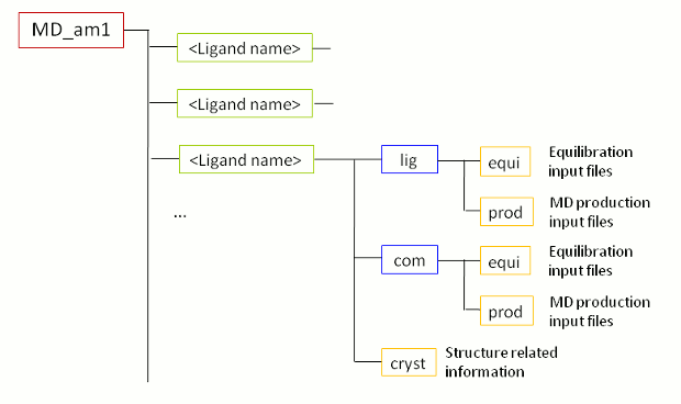
图2: 在步骤1B中由FEW创建的MD文件夹结构示意图
现在, 调用MD_am1文件夹中的shell脚本qsub_equi.sh来开始MD模拟.
/home/user/tutorial/MD_am1/qsub_equi.sh
当完成了所有配体/复合物的平衡阶段, 就可以通过调用MD_am1文件夹中相应的shell脚本来开始生产阶段.
/home/user/tutorial/MD_am1/qsub_MD.sh
注意: 如果您不想运行MD模拟, 您可以将$FEW/examples/tutorial中的整个MD_am1文件夹复制到你的tutorial文件夹下.
利用得到的MD模拟的轨迹, 可以继续设置后面的自由能计算.
第二节: MM-PB(GB)SA 计算
在MM-PBSA和MM-GBSA方法中, FEW都支持使用隐式溶剂分子力学计算结合自由能. 设置MM-PB(GB)SA计算的先决条件是在MD模拟文件夹中已经有MD轨迹, 本例中通过FEW的MD设置功能生成这些轨迹(参见本教程的步骤1A和1B). FEW允许通过1-轨迹和3-轨迹方法准备MM-PB(GB)SA计算[1]. 对于在本教程第一节(表1)中已经准备好的三种因子Xa抑制剂的MD模拟, 这两种方法在这里都将作为可选方案.
有关MM-PB(GB)SA方法的基本介绍, 请参阅文献和高级教程A3. 在教程A3中阐述的结合自由能ΔGbind, solv计算的基本原理也适用于本教程中进行的计算. 然而, 由于假定配体结合时构型熵的变化没有显着差异, 所以不考虑熵对结合的贡献. 故, 我们将这里通过FEW工具依据MM-PB(GB)SA方法计算得到的结合能称为有效结合能, ΔGeffective.
请注意: 这里使用的MM-PB(GB)SA计算样本是基于本教程第一部分准备的2 ns MD模拟的快照. 因此, 不能期望用于计算的快照代表完全平衡的结构. 此外, 所考虑的快照数量较少, 进一步增加了预测的不确定性. 故, 这里展示的MM-PB(GB)SA计算只应被看作是演示FEW功能的一个例子. 对于任何“现实生活”的研究, 强烈建议彻底分析MD轨迹, 以确定用于MM-PB(GB)SA计算的代表性结构集, 因为只有基于这样的集合进行的MM-PB(GB)SA计算才可得到精确的结合能预测. 有关平衡状态考察的一些基本分析可以在教程A3第2节中找到.
A: 3-轨迹方法
由于我们已经根据第一节的3-轨迹方法设置和运行了MD模拟, 所以我们可以直接从MM-GBSA的设置开始, 3-轨迹方法的计算使用FEW命令文件ana_am1_3trj_pb0_gb2.
| bash | |
|---|---|
1 2 3 4 5 6 7 8 9 10 11 12 13 14 15 16 17 18 19 20 21 22 23 24 25 26 27 28 29 30 31 32 33 34 35 36 37 38 39 40 41 42 43 44 45 46 47 48 49 50 51 52 53 54 55 56 57 58 59 60 61 62 63 64 65 66 67 68 69 70 71 72 73 74 75 76 77 78 79 80 81 82 83 84 85 86 87 88 89 90 91 92 93 94 95 96 97 98 99 100 101 102 103 104 105 106 107 108 109 110 111 112 113 114 115 116 117 118 119 120 121 122 123 124 125 126 127 128 129 130 131 132 133 134 | @WAMM
################################################################################
# Command file for MM-PBSA / MM-GBSA calculations based on trajectories
# generated by molecular dynamics simulations previously.
################################################################################
# Location and features of input and output directories / file(s)
#
# lig_struct_path: Folder containing the ligand input file(s)
# output_path: Basis directory in which all setup and analysis folders will
# be generated. The directory needs to be identical with the
# 'output_path' directory used for setup of the MD simulations.
lig_struct_path /home/user/tutorial/structs
output_path /home/user/tutorial
# Receptor features
# water_in_rec: Water present in receptor PDB structure
# used for setup of MD simulations
water_in_rec 1
################################################################################
# General Parameters for MM-PBSA / MM-GBSA calculation setup
#
# mmpbsa_calc: Setup MM-PBSA / MM-GBSA calculations
# 1_or_3_traj: "1" or "3" trajectory approach
# charge_method: Charge method used for MD, either "resp" or "am1"
# additional_library: If an additional library file is required, e.g. for
# non-standard residues present in the receptor structure,
# this file must be specified here.
# additional_frcmod: If additional parameters are needed, e.g. for describing
# non-standard residues present in the receptor structure,
# a parameter file should be provided here.
# mmpbsa_pl: Path to mm_pbsa.pl script
mmpbsa_calc 1
1_or_3_traj 3
charge_method am1
additional_library /home/user/tutorial/input_info/CA.lib
add_frcmod
mmpbsa_pl $AMBERHOME/bin/mm_pbsa.pl
################################################################################
# Parameters for coordinate (snapshot) extraction
#
# extract_snapshots: Request coordinate (snapshot) extraction
# snap_extract_template: Template file for extraction of coordinates from
# trajectory, i.e. input-file for mm_pbsa.pl; only
# required if non-standard input-file shall be used.
# image_trajectories: If set to "1" solutes of the specified trajectories
# will be imaged to the origin before coordinates are
# extracted. Please regard that this may require a large
# amount of additional disc space.
# trajectory_files: Trajectory files to regard. The path will be determined
# automatically. Specify 'all' to regard all trajectories
# files produced in MD. This ensures consistent snapshot
# numbering. Subsets of snapshots will be generated according
# to the parameters first_snapshot, last_snapshot, and
# offset_snapshots. If only a subset of the available MD
# trajectories shall be used, the individual files must be
# specified as 'trajectory_files ' providing
# one entry per line.
# first_snapshot: First structure that shall be extracted from trajectory
# last_snapshot: Last structure that shall be extracted from trajectory
# offset_snapshots: Frequency of structure extraction
#
snap_extract_template
image_trajectories 1
#
trajectory_files all
#
first_snapshot 1
last_snapshot 100
offset_snapshots 1
################################################################################
# MM-PBSA / MM-GBSA Analysis
# mmpbsa_template: Template file for MM-PBSA / MM-GBSA analysis - File used
# as input-file for mm_pbsa.pl; only required if non-standard
# file shall be used.
# PB: If not zero PB calculation will be performed
# Options: "0" -> No PB
# "1" -> PB with calculation of the non-polar part of the
# solvation free energy using the Method developed by
# Tan et al. (J. Phys. Chem. B, 2007, 111, 12263-12274).
# This method can only be run in combination with GB=1
# or GB=0.
# "2" -> Hybrid model developed by H. Gohlke and A. Metz
# with IVCAP=5 and CUTCAP=50
# "3" -> PB with MS=1 and Parse radii
# "4" -> PB with MS=1 and mbondi radii. This method can only
# be combined with GB=1 or GB=0.
# GB: If not zero GB calculation will be performed
# Options: "0" -> No GB
# "1", "2", "5" -> GB analysis according to 'igb' (see manual)
#
# decomposition: If larger 0 energy decomposition of specified type is
# performed. Options: 1-4 - See Amber manual for decomposition
# type options. Decomposition only works with PB=4 and GB=1.
# SASA is calculated by the ICOSA method.
# no_of_rec_residues: Number of residues in the receptor structure
#
# total_no_of_intervals: Total number of intervals to analyze.
# The total_no_of_intervals needs to be consistent with
# the number of 'first_PB_snapshot', 'last_PB_snapshot',
# and 'offset_PB_snapshots' definitions below. Setting
# total_no_of_intervals to a value larger than 1, is
# usually only necessary if snapshots with different
# offsets shall be analyzed.
# first_PB_snapshot: Structure to start analysis with
# last_PB_snapshot: Last structure to regard in analysis
# offset_PB_snapshots: Specification of offset between structures that shall
# be regarded in the MM-PBSA calculation
#
# mmpbsa_batch_template: Batch script template for MM-PBSA calculation
# mmpbsa_batch_path: Optional, path to regard as basis path for batch script
# setup, in case it differs from .
#
# mmpbsa_sander_exe: Optional, Sander executable can be defined here if not
# the default executable in $AMBERHOME/bin shall be
# used for carrying out the MM-PB(GB)SA calculations.
# parallel_mmpbsa_calc: No. of processors to use for parallel run
mmpbsa_template
PB 0
GB 2
#
decomposition 0
no_of_rec_residues 290
#
total_no_of_intervals 1
first_PB_snapshot 51
last_PB_snapshot 100
offset_PB_snapshots 1
#
mmpbsa_batch_template /home/user/tutorial/input_info/MMPBSA.sge
mmpbsa_batch_path /home/user/tutorial
#
mmpbsa_sander_exe
parallel_mmpbsa_calc 1
|
这个命令文件由以下几个部分组成:
- 输入和输出目录/文件的位置:
与本教程第1节中讨论的输入/输出信息部分相同. - MM-PBSA / MM-GBSA计算设置的一般参数:
使用由AM1-BCC方法确定的配体原子电荷产生MD轨迹, 并根据3-轨迹方法准备MM-GBSA计算(1_or_3_traj=3). 为了在没有水的情况下设置拓扑文件, 再次使用钙离子的附加库文件, 并且使用位于本地AMBER安装目录中的bin文件夹下的mm_pbsa.pl脚本进行MM-GBSA分析. - 坐标(快照)提取的参数:
请求在从本教程的第1节生成的2 ns轨迹快照中没有间隔(offset_snapshots=1)的提取1到100帧的镜像快照. - MM-PBSA / MM-GBSA分析:
根据Onufriev[6]等人的方法计算MM-GBSA, 相应的, 在AMBER12中需要设置igb=2. 结构上结合的离子被认为是受体的一部分, 因此受体残基的总数达290. 计算快照51至100的部分, 间隔为1.
计算参数设置为将/home/user/tutorial目录作为基本输入/输出目录以串行方式运行mm_pbsa.pl. 批处理脚本MMPBSA.sge作为作业提交的模板批处理文件. 请根据您的计算环境配置修改此脚本中Prepare calculation前面的部分.
运行FEW:
如果确保在命令文件中正确指定了基本输入/输出目录的路径, 则可以使用以下命令开始基于FEW工具MM-GBSA计算的设置:
$FEW/FEW.pl MMGBSA /home/user/tutorial/cfiles/mmpbsa_am1_3trj_pb0_gb2
输出:
在成功完成FEW运行之后, 在基本输入/输出目录(即tutorial目录)中会出现一个名为calc_a_3t的新文件夹. 该文件夹(图3)根据所采用的方法命名(a=am1, 3t=3-trajectory approach), 其中包含每个配体的子文件夹, 配体文件夹中包含: 不含水的拓扑(文件夹topo), 提取的快照 (文件夹snapshots)以及MM-GBSA计算的输入文件(文件夹s51_100_1).
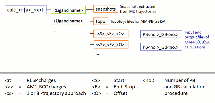
图3: 由FEW创建的MM-PB(GB)SA计算的文件夹结构示意图.
执行位于calc_a_3t文件夹中的qsub_s51_100_1_pb0_gb2.sh脚本以启动MM-GBSA计算.
/home/user/tutorial/calc_a_3t/qsub_s51_100_1_pb0_gb2.sh
计算的结果文件将会出现在文件夹/home/user/tutorial/calc_a_3t/<ligand name>/s51_100_1/pb0_gb2中
因为如果研究十个或更多的配体, 查找所有配体的各自的结果会是一个大规模的工作, 所以FEW中提供了一个允许自动提取最终ΔGbind, effective和各自ΔE贡献的脚本. 该脚本需要一个文本文件, 用来指定需要考虑的配体的名称(每行一个名称), 如:
File: structs.txt
L51c
L51d
L51g
要执行该脚本, 请进入/home/user/tutorial/calc_a_3t文件夹并通过以下方式调用脚本:
perl $FEW/miscellaneous/extract_WAMMenergies.pl structs.txt /home/user/tutorial/calc_a_3t pb0_gb2 51_100_1
最后一项由“_”分隔, 分别对应于first_PB_snapshot, last_PB_snapshot和offset_PB_snapshots. 运行结束后, 您将在/home/user/tutorial/calc_a_3t文件夹中找到一个名为pb0_gb2.txt的文件, 里面汇总了最终结果(请参见下文).
pb0_gb2.txt
Ligand    ELE        VDW       NP_SOLV    P_SOLV    E_TOT
L51c      -192.36    -64.05    -4.80      189.55    -59.35
L51d       -30.70    -62.01    -2.52       36.15    -48.68
L51g      -103.96    -76.04    -4.92      113.28    -66.07
在该文件中给出的能量贡献对应于配体结合时的能量变化, 即复合物的形成过程, 分别为:
ELE静电能量VDW范德华相互作用NP_SOLV非极性溶剂自由能P_SOLV极性溶剂自由能E_TOT总结合能, 即ΔGeffective
计算出的相对结合能显示了预期的趋势. 尽管平均有效结合能的发现是有希望的, 但是我们不应该忘记在MM-GBSA计算中考虑的构象集合的尺度之小(仅考虑来自2ns MD模拟的50个快照). 当你在文件/home/user/tutorial/calc_a_3t/L51c/s51_100_1/pb0_gb2/L51c_statistics.out.snap中的DELTA部分寻找例子时, 您会发现为单个快照计算的ΔGeffective值可以从约-165.6至+84.07 kcal/mol. 因此标准偏差很高(60.8 kcal/mol). 计算能量大幅度波动的一个重要因素是内能中的噪音. 在3-轨迹方法中, 复合物, 受体和配体的内能不会相互抵消, 因此即使结构之间的微小差异也可以对计算出的结合能量产生很大的影响. 在1-轨迹方法中避免了这种噪音, 该方法仅根据复合物的结构计算结合能量, 不考虑配体和受体的游离形式.
B: 1-轨迹方法
尽管事实上在所谓的1-轨迹方法中只考虑了来自复合物模拟的结构, 即未考虑受体和配体在未结合和结合前后的结构差异, 因此这种方法经常被应用并且表明具有良好的相对结合能预测能力. 这种方法的一大优点是对计算的要求较低, 因为只考虑了复合物的MD模拟. 此外, 该方法还可以消除内能的贡献, 从而具有更低的ΔE噪音值.
因此, 由于经常使用1-轨迹方法来估计相对配体结合能, 这里也将演示基于这种方法的MM-PB(GB)SA计算的设置. 一般步骤与上述的3-轨迹方法所示的步骤一样. 我们可以按照步骤2A进行. 首先为FEW创建一个名为mmpbsa_am1_1trj_pb3_gb0的命令文件, 它与上面展示的mmpbsa_am1_3trj_pb0_gb2文件一致. 然后设置1_or_3_traj=1, GB=0和PB=3. 因为这里将执行在计算上更费时的泊松-玻尔兹曼计算, 所以可通过设置first_PB_snapshot=81来减少考虑的快照的数量以节省计算时间. 如果您现在使用此命令文件运行FEW, 则会根据1-轨迹方法获取带有解析半径的MM-PBSA计算的输入文件. 计算的最终结果如下所示. 尽管模拟时间短, 所考虑的快照数量较少, 并且通过1-轨迹方法进行的近似, 但计算的结合能ΔGeffective(E_TOT)依然显示了这些配体的预期趋势(参见表1).
pb3_gb0.txt
Ligand   ELE      VDW      NP_SOLV    P_SOLV    E_TOT
L51c     -19.05   -61.20   -6.20      61.16     -25.28
L51d     -20.54   -64.81   -6.27      69.46     -22.17
L51g     -21.64   -65.20   -6.28      66.50     -26.62
第三节: 线性相互作用能分析
FEW提供了根据线性相互作用能(LIE)方法[3, 4]进行结合自由能计算的功能. 在这种方法中, 结合自由能由复合物形成前后配体与其环境之间的静电(ELE)和范德华力(VDW)相互作用能的变化来计算. 相互作用能贡献的计算中, 不管自由的配体还是与受体结合的配体, 都是从模拟快照中溶液体系的总能量里减去各组分的能量来确定的(图4). 能量是由使用sander程序单点计算确定的. 用户选择的用于分析的构象集里每个快照中的相互作用能都会被计算并取所有构象的平均值.
结合自由能被认为是范德华和静电相互作用能各自的差并考虑各自权重因子的总和(参见图4中的最后一个方程). FEW使用公认的权重因子提供所研究的目标体系中配体结合自由能的粗略估计.
注意: 尽管已经证明了所采用的比例因子具有良好的结合自由能估计能力, 但对于所有的蛋白质-配体系统来说, 情况可能并非如此(参见[7]中更详细的讨论). 因此, 对特定的配体-蛋白质系统来说, 强烈建议彻底考查是否有其他更合适的其他权重因子. 如果已经通过实验确定了一些研究的化合物的结合亲和力, 则最佳的权重因子应该由计算的结合能与实验确定的结合能进行线性拟合来确定.
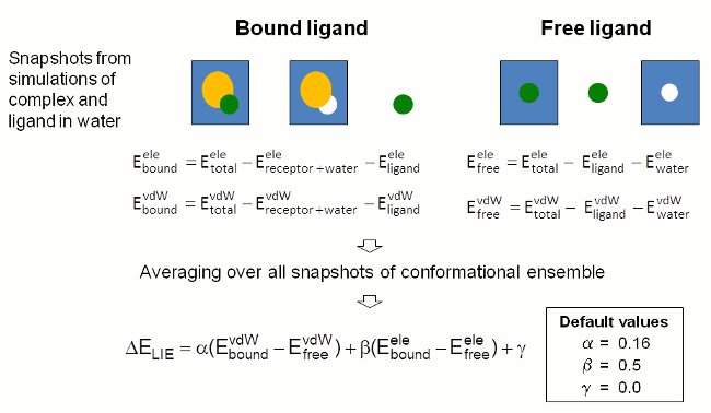
图4: FEW中用于通过LIE方法计算配体结合自由能的步骤示意图.
用FEW设置LIE分析的先决条件是使用FEW的MD设置功能已经生成了溶液中配体和复合物的轨迹. 因为我们在本教程的第一部分中MM-PBSA计算的3-轨迹设置时创建了这样的轨迹, 这些必要的信息已经有了. 用于准备LIE分析的命令文件lie_am1位于/home/user/tutorial/cfiles目录中.
提示: 如果您只准备执行LIE计算, 请使用traj=3设置MD模拟, 那么FEW程序调用时就使用LIE而不是MMPBSA方法. 通过这种方式, 只准备了复合物和配体的MD模拟, 而没有设置对于LIE分析来说多余的受体模拟.
| bash | |
|---|---|
1 2 3 4 5 6 7 8 9 10 11 12 13 14 15 16 17 18 19 20 21 22 23 24 25 26 27 28 29 30 31 32 33 34 35 36 37 38 39 40 41 42 43 44 45 46 47 48 49 50 51 52 53 54 55 56 57 58 59 60 61 62 63 64 65 66 67 68 69 70 71 72 73 74 75 76 77 78 79 80 81 82 83 84 85 86 87 88 89 90 91 92 93 94 95 96 97 98 99 | @LIEW
################################################################################
# Command file for LIE calculations based on trajectories
# generated by molecular dynamics simulations previously.
################################################################################
# Location and features of input and output directories / file(s)
#
# lig_struct_path: Folder containing the ligand input file(s)
# output_path: Basis directory in which all setup and analysis folders will
# be generated. The directory needs to be identical with the
# 'output_path' directory used for setup of the MD simulations.
lig_struct_path /home/user/tutorial/structs output_path /home/user/tutorial
# Receptor features
# water_in_rec: Water present in receptor PDB structure
# used for setup of MD simulations
water_in_rec 1
################################################################################
# General Parameters for LIE calculation setup
#
# lie_calc: Request setup of LIE calculations
# charge_method: Charge method used for MD, either "resp" or "am1"
# no_of_rec_residues: Number of residues in receptor structure
# additional_library: If an additional library file is required, e.g. for
# non-standard residues present in the receptor structure,
# this file must be specified here.
# additional_frcmod: If additional parameters are needed, e.g. for describing
# non-standard residues present in the receptor structure,
# a parameter file should be provided here.
# lie_executable: Location of LIE calculation script provided with FEW.
# If no script is specified, it is assumed that the LIE
# program is located in the default directory.
# lie_batch_template: Template batch file for LIE calculation
# lie_batch_path: Path to regard as basis path for setup of batch files
#
lie_calc 1
charge_method am1
no_of_rec_residues 290
additional_library /home/user/tutorial/input_info/CA.lib
additional_frcmod
lie_executable
lie_batch_template /home/user/tutorial/input_info/lie.sge
lie_batch_path
#
################################################################################
# Parameters for coordinate extraction
#
# image_trajectories: If set to "1" solutes of the specified trajectories
# will be imaged to the origin before coordinates are
# extracted. Please regard that this may require a large
# amount of additional disc space.
# trajectory_files: Trajectory files to regard. The path will be determined
# automatically. Specify 'all' to regard all trajectories
# produced in the production phase of the MD simulations.
# This ensures consistent snapshot numbering.
# Subsets of snapshots will be generated according to the
# parameters first_lie_snapshot, last_lie_snapshot, and
# offset_lie_snapshots. If only a subset of the trajectories
# from MD shall be used, the individual files must be
# specified as 'trajectory_file ' providing one
# entry per line.
# ATTENTION: The trajectory file(s) must exist for both the
# simulation of the complex and the simulation of
# the free ligand in solution.
# snaps_per_trajectory: Number of snapshots stored in each trajectory.
#
image_trajectories 1
#
trajectory_files md_prod_001.mdcrd.gz
trajectory_files md_prod_002.mdcrd.gz
#
snaps_per_trajectory 50
################################################################################
# LIE Analysis
#
# calc_sasa: Request calculation of change in solvent accessible surface area
# first_lie_snapshot: No. of snapshot from which the LIE calculation
# shall be started
# last_lie_snapshot: No. of last snapshot that shall be regarded in the
# LIE calculation
# offset_lie_snapshots: Offset between snapshots that shall be regarded
# in the LIE calculation
# sander_executable: Sander executable that shall be used for the LIE
# calculation, if this differs from the default one
# in $AMBERHOME/bin
# parallel_lie_call: Call for running sander in parallel, e.g.:
# mpirun -np 2 -machinefile $PBS_NODEFILE
# Prerequisite: Parallel version of sander installed
# delete_lie_trajectories: Delete trajectory files created for LIE analysis
# directly after energy calculation
#
calc_sasa 0
first_lie_snapshot 81
last_lie_snapshot 100
offset_lie_snapshots 1
sander_executable
parallel_lie_call mpirun -np 8
delete_lie_trajectories 0
|
LIE分析的FEW脚本由以下几个部分组成:
- 输入和输出目录/文件的位置:
这里定义了输入/输出的具体参数. 本脚本的这一部分与之前展示的其他命令文件的对应部分相同(参见第1节). - 设置LIE计算的一般参数:
本例中LIE分析是基于配体电荷为am1电荷的MD模拟设置的. 因为受体的290个残基中存在结合的钙离子, 所以需要加载一个额外的库文件. 假设可执行文件LIE.pl位于默认位置, 并且使用基本输入/输出目录作为输出目录来设置LIE计算. 设置LIE计算的批处理文件的模板由lie_batch_template指定. 在准备计算前, 此模板文件中的设置需要根据执行LIE计算的计算环境修改. - 坐标提取参数:
这部分命令文件与本教程第2节中介绍的MM-PB(GB)SA计算的命令文件的快照提取部分类似. 在坐标提取前需要准备轨迹文件. 在MD生产过程中产生的所有轨迹都被指定. 这是确保正确识别快照坐标所必需的. 在LIE计算中将被考虑的快照是基于每个轨迹文件snaps_per_trajectory中存在的快照的数量以及下面第4点中描述的first_lie_snapshot, last_lie_snapshot和offset_lie_snapshots来选择的. - LIE分析的参数:
LIE分析是在快照81至100间, 间隔(offset)为1的条件下进行的. FEW提供了计算配体溶剂可及表面积在结合态和游离态之间的差异的可能性, 因为这个量已经用于确定配体特异性系数γ(参见图4中的最后一个方程)[8, 9, 10]. 但是, 这里没有选择这个选项(calc_sasa=0). 这里提供了一个专门针对sander的并行计算环境项parallel_lie_call. 因此, 将使用sander的并行版本$AMBERHOME/bin/sander.MPI运行LIE分析. 因为从原始MD轨迹生成的用于LIE分析的轨迹中包含水分子而占用大量的磁盘空间, 所以在一个配体的LIE计算完成之后, FEW提供了一个直接删除这些轨迹中水分子的选项. 这个选项在这里没有打开(delete_lie_trajectories=0).
提示: 如果您要使用大量快照通过LIE分析来计算结合自由能, 请首先使用少量快照设置LIE计算, 并检查所创建的文件的占用磁盘空间大小, 然后估计, 计算机系统是否有足够的空间满足您基于大量快照的LIE计算的需求.
运行FEW:
当调整好了特定的计算环境设置, 并且命令文件中的基本输入/输出路径也已被正确指定时, 就可以使用FEW来准备LIE计算了.
perl $FEW/FEW.pl LIE /home/user/tutorial/cfiles/lie_am1
输出:
成功运行FEW后, 目录/home/user/tutorial中会出现一个名为lie_am1的新文件夹, 其子结构如图5所示. 请注意, 图5中紫色的有关能量计算结果的文件夹尚未出现. 它们将在LIE计算的过程中创建.
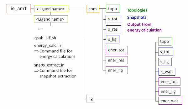
图5: 使用FEW进行LIE分析时创建的文件夹及其子结构示意图.
开始LIE计算:
LIE计算可以通过执行位于文件夹lie_am1中的shell脚本qsub_LIE.sh来启动.
/home/user/tutorial/lie_am1/qsub_LIE.sh
LIE结果:
LIE计算的最终结果可以在目录/home/user/tutorial/lie_am1中配体文件夹的特定子文件夹中找到. 文件LIE_s<S>_<T>_<O>.txt(<S>=first_lie_snapshot, <T>=last_lie_snapshot, <O>=offset_lie_snapshots), 如本教程中的文件LIE_s81_100_1.txt, 列出了结合状态的复合物与游离配体的静电相互作用和vdW相互作用能(以及溶剂可及表面积)的平均计算结果, 以及它们的差值. 需要额外说明的是, 这里结合自由能的评估使用了图4中给出的缩放因子.
Result file LIE_s81_100_1.txt of ligand L51c
Energy contributions:
						   Mean energy    Standard deviation    Standard error
Complex non-bonded VDW:     -76.550390              3.354497          0.750088
Complex non-bonded ELE:     -49.058070              7.613551          1.702442
Ligand non-bonded VDW:      -43.399665              3.762162          0.841245
Ligand non-bonded ELE:      -56.828235              6.755975          1.510682

================================================================================
Final LIE results:

Differences in interaction energies and SASA:

Delta electrostatic energy (dE-ele):      7.770165 kcal/mol
Delta van der Waals energy (dE-vdW):    -33.150725 kcal/mol
________________________________________________________________________________

Estimated binding free energy:

ATTENTION: Please note that the estimate of the binding free energy (dG-bind)
		   provided below was calculated according to the equation
		   dG-bind = alpha * dE-vdW + beta * dE-ele
		   with fixed coefficients of alpha=0.16 and beta=0.5.
		   We strongly recommend to thoroughly investigate whether using other
		   coefficients could be beneficial in the specific case.

Binding energy estimate (dG-bind):       -1.419034 kcal/mol
提示: 如果您希望通过线性拟合为一个已知实验结合亲和力的数据集的确定最佳的加权系数, 则可以使用FEW提供的脚本extract_LIEenergies.pl从所有结果的数据集中提取出静电以及vdW相互作用能的(结合与游离态)差值(“溶剂可及表面积”项也一样). 详情请参阅FEW手册.
第四节: 热力学积分的计算
FEW工具可以很方便的通过热力学积分(TI)方法确定不同配体结合相同受体的相对结合自由能. 该程序提供了所需的热力学积分(TI)转换模拟的自动化设置的功能, 并在最少的用户干预下依据这些模拟的结果计算配体的相对结合自由能.
TI方法确定相对结合自由能的基本原理在高级教程A9中有解释. 这里只演示使用FEW工具设置TI计算. 使用FEW的设置与高级教程A9中的设置不同, 主要在于每次转换只进行一次模拟(而不是三次), 即一个是在水中进行转换模拟, 一个是在溶剂化的复合物中进行转换模拟. 由FEW工具准备的模拟依据1步软核法(参见[11]和Amber14手册第355页), 该方法允许在单个模拟中改变电荷和vdW相互作用.
这里通过计算因子Xa的配体L51c和L51d的相对结合自由能(图6)来演示FEW的TI计算设置功能. 使用第1节中的MD模拟得到的L51c的平衡状态的配体和复合物结构作为输入结构.
注意: 尽管这里采用预先平衡过的结构进行TI设置, 但原则上依据步骤1A设置了参数并依据步骤1B生成了溶剂系统的任何复合物和配体结构都可以开始TI计算. 如果您打算从非平衡结构开始进行TI模拟, 请参考FEW手册.
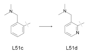
图6: TI方法的转换研究.
为准备输入结构和参数以及设置TI MD平衡相和生产相计算, 使用了一个名为TI_setup_L51c_d.in的命令文件. 通过将命令文件中的相应部分标志设置为1来请求不同的任务(下面的步骤1A - 2B).
| TI_setup_L51c_d.in | |
|---|---|
1 2 3 4 5 6 7 8 9 10 11 12 13 14 15 16 17 18 19 20 21 22 23 24 25 26 27 28 29 30 31 32 33 34 35 36 37 38 39 40 41 42 43 44 45 46 47 48 49 50 51 52 53 54 55 56 57 58 59 60 61 62 63 64 65 66 67 68 69 70 71 72 73 74 75 76 77 78 79 80 81 82 83 84 85 86 87 88 89 90 91 92 93 94 95 96 97 98 99 100 101 102 103 104 105 106 107 108 109 110 111 112 113 114 115 116 117 118 119 120 121 122 123 124 125 126 127 128 129 130 131 132 133 134 135 136 137 138 139 140 141 142 143 144 145 146 147 148 149 150 151 152 153 154 155 156 157 158 159 160 161 162 | @TIW
################################################################################
# Command file for TI simulation setup
################################################################################
# Location of input and output directories / file(s)
#
# lig_struct_path: Folder containing the ligand input file(s)
# output_path: Basis directory in which all setup and analysis folders will
# be generated. The directory must be identical with the
# 'output_path' directory used for setup of the MD simulations.
lig_struct_path /home/user/tutorial/structs
output_path /home/user/tutorial
################################################################################
# Parameters required for TI simulation setup:
# The following parameters have to be specified and need to be identical
# in all subsequent runs for one system / TI-setup
#
# ti_simulation_setup: Request setup of TI simulation
# charge_method: Charge method that shall be used, either "resp" or "am1"
# lig_name_v0_struct: Name of start-ligand - Must be identical to the name of
# the file in the "structs" folder used for generation of
# parameter and library files with the common MD setup
# functionality of FEW.
# lig_name_v1_struct: Name of end-ligand - Must be identical to the name of
# the file in the "structs" folder used for generation of
# parameter and library files with the common MD setup
# functionality of FEW.
# lig_alias_v0: Alias that shall be used for the identification of the
# start-ligand. The alias must consist of 3 characters.
# lig_alias_v1: Alias that shall be used for the identification of the
# end-ligand. The alias must consist of 3 characters.
# softcore_mask_v0: Soft core atom mask for start-structure, specifying the
# atoms of the start-structure (state V0) that shall be
# regarded as soft core using the format
# <lig_alias_v0>@<atom name list separated by comma>
# softcore_mask_v1: Soft core atom mask for end-structure, specifying the
# atoms of the end-structure (state V1) that shall be
# regarded as soft core using the format
# <lig_alias_v1>@<atom name list separated by comma>
ti_simulation_setup 1
charge_method am1
lig_name_v0_struct L51c
lig_name_v1_struct L51d
lig_alias_v0 LFc
lig_alias_v1 LFd
softcore_mask_v0 LFc@C14,H1
softcore_mask_v1 LFd@N3
#
################################################################################
# 1) Parameters for preparation of coordinate and topology files of solvated
# systems of start- and end-structures for TI simulations
#
# A) Generation of atom association list based on ligand mol2 files of
# start and end structures
#
# prepare_match_list: Request creation of matching list
prepare_match_list 1
#
# B) Setup of coordinate and topology files
#
# It is required that RESTRT (coordinate) and topology files for the ligand and
# complex of the start structure exist. These can be generated with the common
# MD setup functionality of FEW.
#
# prepare_inpcrd_prmtop: Request setup of coordinate and topology files
# lig_inpcrd_v0: Coordinate file (restart file) of ligand - start structure
# com_inpcrd_v0: Coordinate file (restart file) of complex - start structure
# lig_prmtop_v0: Topology of ligand - start structure
# com_prmtop_v0: Topology of complex - start structure
# match_list_file: Optional: File containing the atom association information
# for the common part of start- and end-structures. Must only
# be specified if step 1A was not successful and the list was
# created manually.
# chain_termini: Comma separated numbers of terminal residues of chains in
# receptor structure.
# create_sybyl_mol2: Request generation of mol2-files with sybyl atom types
# for easy comparison of atom names of start- and end-
# structures. Can facilitate checking and manual adjustment
# of atom names in the end-structure, if automatic matching
# is not successful.
# additional_library: If an additional library file is required, e.g. for
# non-standard residues present in the receptor structure,
# this file must be specified here.
# additional_frcmod: If additional parameters are needed, e.g. for describing
# non-standard residues present in the receptor structure,
# a parameter file should be provided here.
# SSbond_file: File with disulfide bridge definitions
#
prepare_inpcrd_prmtop 1
lig_inpcrd_v0 /home/user/tutorial/MD_am1/L51c/lig/equi/md_nvt_red_06.restrt
com_inpcrd_v0 /home/user/tutorial/MD_am1/L51c/com/equi/md_nvt_red_06.restrt
lig_prmtop_v0 /home/user/tutorial/MD_am1/L51c/cryst/L51c_solv_lig.top
com_prmtop_v0 /home/user/tutorial/MD_am1/L51c/cryst/L51c_solv_com.top
match_list_file
chain_termini 235
create_sybyl_mol2 1
additional_library /home/user/tutorial/input_info/CA.lib
additional_frcmod
SSbond_file /home/user/tutorial/input_info/disulfide_bridges.txt
# 2) Setup scripts for TI MD
#
# General parameters
#
# no_shake: Set to "1", if no SHAKE shall be performed
# ti_batch_path: Root path to be used in setup of batch files
# ti_prod_template: Template script for TI production simulations
no_shake 1
ti_batch_path /home/user/tutorial
ti_prod_template /home/user/tutorial/input_info/MD_prod_noShake_TI.in
#
# A) Setup of scripts for equilibration
#
# ti_equil: Request generation of scripts for TI equilibration input
# ti_equil_template: Template file for equilibration part of equilibration
# phase of TI simulations. This equilibration part is
# followed per default by a 1 ns free TI MD simulation
# for complete equilibration of the system.
# ti_equil_batch_template: Batch template file for equilibration phase of
# TI simulations.
# ti_equil_lambda: Values of lambda that shall be used in the calculation
# in ascending order. Please specify only the decimal digits,
# e.g. 1 for lambda 0.1, 05 for lambda 0.05.
ti_equil 0
ti_equil_template /home/user/tutorial/input_info/equi_noShake_TI.in
ti_equil_batch_template /home/user/tutorial/input_info/equi_TI.sge
ti_equil_lambda 1,2,3,4,5,6,7,8,9
#
# B) Setup scripts for production
#
# ATTENTION: This setup step can only be conducted if the equilibration
# calculations have been completed.
#
# ti_production: Request generation of scripts for TI production input.
# This setup step requires that the equilibration output is
# present in the corresponding 'equi' folder.
# ti_prod_lambda: Lambda steps for which the production shall be run;
# separated by comma and in ascending order. Please specify
# only the decimal digits, e.g. 1 for lambda 0.1.
# total_ti_prod_time: Total production time requested (in ns)
# ti_prod_batch_template: Batch template for TI production simulations
# converge_check_script: Location of perl program to be used for convergence
# checking after each production step. If the location
# is not specified, it will be assumed that the program
# can be found under the default location
# at .../FEW/miscellaneous/convergenceCheck.pl
# converge_check_method: Method that shall be used for convergence checking.
# 1: Difference in standard error of dV/dL
# 2: Precision of dV/dL according to student's
# distribution
# converge_error_limit: Error limit that shall be used as termination criterion
# for the TI production simulations.
# Defaults: 0.01 kcal/mol for method 1
# 0.2 kcal/mol for method 2
ti_production 0
ti_prod_lambda 1,2,3,4,5,6,7,8,9
total_ti_prod_time 1,1,1,1,1,1,1,1,1
ti_prod_batch_template /home/user/tutorial/input_info/prod_TI.sge
converge_check_script
converge_check_method 2
converge_error_limit 0.2
|
全局参数的定义
命令文件中各关键项最前面的部分是用来定义基本输入/输出路径或文件的, 这与第1节中讨论的用于MD模拟设置的命令文件的输入/输出指定部分的关键项相同.
在TI模拟的设置中, 指定配体使用AM1-BCC电荷进行TI模拟. 此外, 配体的名称, 即转换前后MOL2结构文件的名称, 分别由lig_name_v0_struct和lig_name_v1_struct指定, 并被用作转换的名称. 相应的配体别名lig_alias_v0和lig_alias_v1被用作各自的ID并出现在配体残基名和文件名中. 各自的softcore_mask定义了软核原子, 即在将配体L51c转换到配体L51d中时应该改变, “出现”或“消失”的原子, 也就是要去耦合的原子.
步骤1: 输入坐标和拓扑文件的准备
要请求设置TI模拟的坐标和拓扑文件时, 请将参数ti_simulation_setup和prepare_inpcrd_prmtop设置为1.
A: 在实际输入文件准备好之前, 会创建一个原子关联列表, 即两个配体中结构上等价的原子被成对列出. 等价原子的识别是必要的, 因为配体中所有的共同原子后面需要在坐标文件中以相同顺序列出. 因此, 正确的原子关联列表对一个成功的模拟设置来说是必不可少的. 通常来讲, 这一步不需要任何用户干预.
B: 当创建好原子关联列表后, 实际的坐标和拓扑文件也就生成了. 转换模拟的结束状态的文件, 在本例中为L15d, 是基于开始状态的坐标和拓扑文件准备的. 因此, 需要提供溶剂化配体L51c(lig_inpcrd_v0)以及溶剂化复合物(com_inpcrd_v0)的坐标文件. 这些坐标文件是从本教程第一节中MD模拟的准备(和运行)的最终平衡步骤中获得的. 用于模拟的相应的拓扑文件存在于模拟目录的cryst文件夹中, 他们需要在命令文件中的lig_prmtop_v0和com_prmtop_v0下指定.
由于蛋白质因子Xa不是单体, 而是由两条链组成, 所以需要在chain_termini下指定第一条链的末端. 其他具体的受体特征可以通过指定additional_library, additional_frcmod和SSbond_file来设置, 这些在前面已经讲过(见第1节).
运行FEW:
在基本输入/输出路径(即, 此处的路径/home/user/tutorial)已更改为您本地系统上存放教程文件的路径之后, 可以通过以下方式调用FEW:
perl $FEW/FEW.pl TI /home/user/tutorial/cfiles/TI_setup_L51c_d.in
当您将参数ti_simulation_setup和prepare_inpcrd_prmtop设置为1, 并使用上面的命令行运行FEW时, /home/user/tutorial目录中会创建一个名为TI_am1的新文件夹. 该文件夹中包含依据配体名称命名的子文件夹, 这里所说的配体名称根据命令文件中的lig_name_v0_struct和lig_name_v1_struct项确定. 根据此例中命令文件里定义的配体名称, 该文件夹将被命名为L51c_L51d. 所有与这个具体转换模拟相关的数据都会被存入这个子文件夹中(图7). 目前只有setup文件夹存在, 其中包含设置坐标和拓扑文件过程中生成的文件.
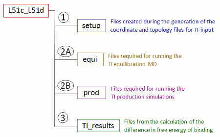
图7: 使用FEW设置TI计算时所创建的转换模拟专用文件夹及其子结构的示意图.
步骤2: TI MD模拟的设置
A: 平衡
可通过将ti_equil设置为1来要求为TI MD模拟的平衡阶段准备文件. 这里, 在不使用Shake算法(no_shake=1)来限制涉及氢原子的键的情况下准备模拟. 脚本中output_path定义的路径也用作准备好的批处理脚本(ti_batch_path)的输入/输出路径. 使用模板ti_equil_template和ti_prod_templ创建模拟中平衡阶段的输入文件, λ值设置为9个, 即0.1,0.2,0.3,0.4,0.5,0.6,0.7,0.8和0.9. 当前情况下, 根据ti_equi_templ中的设置进行纯粹平衡步骤之后是ti_prod_templ中采用的混合1 ns模拟, 以确保彻底平衡. 在使用批处理模板ti_equi_batch_template前, 需要根据本地计算环境的设置调整脚本中Fix variables声明的前面部分和Re-queue部分.
当打开脚本中的ti_equil项重复步骤1中的命令运行FEW后, 在转换模拟专用文件夹L51c_L51d(图7)中会创建一个名为equi的文件夹. 该文件夹包含两个子文件夹, 即lig(溶剂中自由配体模拟)和com(溶剂化的复合物模拟). 每个lig或com文件夹中都包含TI模拟的输入文件和通过排队系统提交作业的批处理脚本run.pbs. TI模拟的平衡步骤可以通过以下方式启动:
qsub /home/user/tutorial/TI_am1/L51c_L51d/equi/com/run.pbs
qsub /home/user/tutorial/TI_am1/L51c_L51d/equi/lig/run.pbs
然后根据图8所示的方案依次处理不同λ值的平衡步骤.
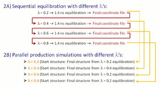
图8: TI模拟平衡和生产阶段的工作流程示意图.
注意:
当完成了所有生产阶段应考虑的λ值的平衡模拟, 下面描述的TI MD模拟的生产阶段的设置就可以开始了. 由于运行平衡模拟非常耗时, 因此在FEW的教程文件夹里提供了记录模拟过程中具体能量的输出文件. 如果您想使用提供的MD输出文件, 请先将文件link_TIequi_output.sh复制到您的基本输入/输出文件夹
cp $FEW/examples/tutorial/link_TIequi_output.sh /home/user/tutorial
接着将文件link_TIequi_output.sh中第三行的路劲/home/src/FEW替换为您本地系统中FEW的安装路径. 然后执行脚本文件.
/home/user/tutorial/link_TIequi_output.sh
然后退出shell并确认在/home/user/tutorial/TI_am1/L51c_L51d/equi下的com和lig文件夹中是否创建了软链接.
B: 生产
转换模拟生产阶段输入文件的准备工作通过将ti_production设置为1来调用. 在这里已经执行了对于九个λ值的平衡阶段的模拟的设置. 也可以要求生产阶段的设置中仅使用平衡阶段中已经运行过的部分λ值. 然而, 前后两个Δλ的大小(即, λ步长)应必须与所有的Δλ相等. 因此, 只对λ值0.2、0.4、0,6和0.8进行模拟也是可能的.
TI生产阶段的模拟是从平衡阶段最终的坐标文件开始的. 精度优于0.2 kcal/mol(根据95%置信水平的t分布)将被用作模拟的终止标准. 如果所有λ值的模拟后没有达到这个标准, 那么模拟将会在total_ti_prod_tim=1 ns后终止. 批处理模板文件ti_prod_batch_template需要按照与上述ti_equil_batch_template文件相同的方式进行修改, 然后作为用于提交TI生产作业的批处理文件的设置模板文件.
运行FEW:
当计算环境的具体修改已经完成时, 可以使用开启了ti_production选项的命令文件来调用使用FEW工具的TI生产阶段模拟的设置.
perl $FEW/FEW.pl TI /home/user/tutorial/cfiles/TI_setup_L51c_d.in
生产阶段的设置从依据反向累积平均方法[12, 13]检查平衡阶段开始的, 以确保系统平衡并可用于TI生产. 检查完后, 会通知您平衡检查是否成功. 在当前的案例中, 对于配体和复合物的所有λ值的膜拟中平衡检查都通过了. 可能会发生整体平衡检查通过, 但对于单个λ的模拟的平衡检查不通过的情况. 在这种情况下, 应进一步分析各个平衡, 以完全排除平衡期间存在的可能降低后续结合自由能预测准确性的任何问题. dV/dλ值与模拟时间的关系图对于识别这些问题是有价值的. 图9展示了从输出文件中提取的一个这样的dV/dλ值曲线图, 以及它们相对于模拟时间绘制的累积平均值(红线). 很显然, 虽然dV/dλ值波动很大, 但是累计平均值却是相对恒定的. 这表明平均而言系统已经处于平衡状态, 并且只需要较长时间的采样以达到与其他λ值相同的精度. 因为通过实施收敛检查确保了生产运行中精度水平的控制, 所以在这种情况下, 平衡阶段的最终结构可以用作生产阶段的输入结构.
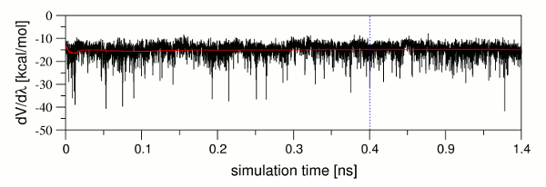
图9: dV/dλ值(黑色)及其累积平均值(红色)与模拟时间的关系图. 纯平衡阶段的结束, 也就是平衡阶段中1 ns生产部分开始的模拟时间点以蓝色虚线表示.
TI生产模拟的文件存放在名为prod的文件夹中. 就像上文描述的equi文件夹一样, 该文件夹中包含两个子文件夹, lig和com, 分别用于模拟溶液中的配体和溶剂化的复合物. 生产模拟可以通过提交批处理脚本开始, 例如:
/home/user/tutorial/TI_am1/L51c_L51d/qsub_prod.sh
注意: 因为对9个λ值的情况下的两个系统进行TI模拟是非常耗时的计算, 所以包含能量值的模拟输出文件可以使用FEW工具给出. 如果您想使用这些文件, 请将脚本copy_TIprod_output.sh复制到tutorial文件夹中
cp $FEW/examples/tutorial/copy_TIprod_output.sh /home/user/tutorial
并将脚本中的路径/home/src/FEW更改为本地系统上FEW的安装目录. 然后执行脚本.
/home/user/tutorial/copy_TIprod_output.sh
脚本完成后, 退出shell并检查TI生产阶段的输出文件是否已复制到/home/user/tutorial/TI_am1/L51c_L51d/prod下的lig和com文件夹中.
步骤3: 计算相对结合自由能
L51c和L51d间的结合自由能之差ΔΔGbinding可以使用FEW工具基于TI生产模拟的输出文件自动计算. 命令文件TI_setup3_L51c_d.in包含此任务所需的参数.
| TI_setup3_L51c_d.in | |
|---|---|
1 2 3 4 5 6 7 8 9 10 11 12 13 14 15 16 17 18 19 20 21 22 23 24 25 26 27 28 29 30 31 32 33 34 35 36 37 38 39 40 41 42 43 44 45 46 47 48 49 | @TIW
################################################################################
# Command file for calculating the difference in binding free energy
# between start and end ligand based on TI simulations.
################################################################################
# Location of input and output directories / file(s)
#
# lig_struct_path: Folder containing the ligand input file(s)
# output_path: Basis directory in which all setup and analysis folders will
# be generated. The directory must be identical with the
# 'output_path' directory used for setup of the MD simulations.
lig_struct_path /home/user/tutorial/structs
output_path /home/user/tutorial
################################################################################
# Parameters required for TI analysis:
#
# ti_ddG: Request calculation of difference in binding free energy.
# charge_method: Charge method that shall be used, either "resp" or "am1"
# lig_name_v0_struct: Name of start-ligand - Must be identical to the name of
# the file in the "structs" folder used for generation of
# parameter and library files with the common MD setup
# functionality of FEW.
# lig_name_v1_struct: Name of end-ligand - Must be identical to the name of
# the file in the "structs" folder used for generation of
# parameter and library files with the common MD setup
# functionality of FEW.
# lig_alias_v0: Alias that shall be used for the identification of the
# start-ligand. The alias must consist of 3 characters.
# lig_alias_v1: Alias that shall be used for the identification of the
# end-ligand. The alias must consist of 3 characters.
# dVdL_calc_source: Specification of files considered in computation of ddG:
# 0: All files available for ligand and complex are considered
# X-Y: Where X is the number of the first and Y is the number
# of the last production file that shall be taken into account.
# If Y=0 all files from X on will be considered.
# ddG_calc_method: Method to be used for the calculation of dG:
# 1: Conventional numerical integration with interpolation
# to lambda=0 and lambda=1.
# 2: Numerical integration without interpolation
#
ti_ddG 1
charge_method am1
lig_name_v0_struct L51c
lig_name_v1_struct L51d
lig_alias_v0 LFc
lig_alias_v1 LFd
dVdL_calc_source 0
ddG_calc_method 1
|
相信大家对这个这个命令文件的输入/输出定义部分已经很熟悉了. 上面的脚本文件中还解释了TI分析部分中配体的具体定义项. 唯一重要的新参数是dVdL_calc_source和ddG_calc_method. 这两个参数中的第一个参数决定了TI生产阶段的哪些文件将用于计算ΔΔGbinding. 这里我们使用TI生产期间创建的所有文件. 当然, 只使用某个模拟时间之后文件中记录的dV/dλ值的模拟文件也是可行的.
这里使用依据梯形法则的常规计算作为ΔΔGbinding的计算方法, 并线性外延到末端λ=0和λ=1状态. 相关可选选项, 请参阅FEW手册和[13].
使用TI_setup3_L51c_d.in命令文件执行FEW工具后, 可以在转换专用目录中找到一个名为TI_results的新文件夹(图7). 此文件夹包含列出了计算ΔΔGbinding时所考虑的所有dV/dλ值的文本文件, 一个日志文件和一个名为TI_dG.out的文件, TI_dG.out中提供了最终结果.
计算得到的L51c和L51d之间的结合自由能差异是2.00 kcal/mol. 请记住这是一个非常粗略的结合自由能的评估, 因为在1 ns的短暂模拟时间内, dV/dλ值没有达到所有λ的期望误差下限. 尤其是在复合物状态下λ=0.8和0.9的误差仍然很高. 还应该记住, 这里应用的转换是非常小的, 所以生产模拟可以相对较快地收敛, 对于其他转换, 可能需要更长的模拟才能获得良好的预测效果.
